LINE THERMAL PRINTER
MODEL CT-D101
User’s Manual
Radio Wave Interference Self-Regulation
|
This device is a Class A device.
Using this device in a residential environment may cause radio wave interference.
In this case, the user may be required to take an appropriate measure.
VCCI-A
|
GENERAL PRECAUTIONS
- Before using this product, be sure to read through this manual. After having read
this manual, keep it in a safe, readily accessible place for future reference.
- The information contained herein is subject to change without prior notice.
- Reproduction or transfer of part or all of this document in any means is prohibited
without permission from Citizen Systems.
- Note that Citizen Systems is not responsible for any operation results regardless
of omissions, errors, or misprints in this manual.
- Note that Citizen Systems is not responsible for any trouble caused as a result of
using options or consumables that are not specified in this manual.
- Except explained elsewhere in this manual, do not attempt to service, disassemble,
or repair this product.
- Note that Citizen Systems is not responsible for any damage attributable to incorrect
operation/handling or improper operating environments that are not specified in this
manual.
- Data is basically for temporary use and not stored for an extended period of time
or permanently. Please note that Citizen Systems is not responsible for damage or
lost profit resulting from the loss of data caused by accidents, repairs, tests or
other occurrences.
- If you find omissions, errors, or have questions, please contact your Citizen Systems
dealer.
- If you find any pages missing or out of order, contact your Citizen Systems dealer
for a replacement.
|
- EPSON and ESC/POS are registered trademarks of Seiko Epson Corporation.
- QR Code is a registered trademark of DENSO WAVE INCORPORATED.
- Ethernet is a registered trademark of Fuji Xerox Corporation.
- CITIZEN is a registered trademark of Citizen Watch Co., Ltd.
- All other trademarks are the property of their respective owners.
- Citizen Systems use these trademarks in accordance with the license of relevant owners.
Copyright© CITIZEN SYSTEMS JAPAN CO., LTD. 2021
PRECAUTIONS ON PRINTER INSTALLATION
 WARNING
|
- Do not use or store this product in a place where it will be exposed to:
-
- Flames or moist air.
- Direct sunlight.
- Hot airflow or radiation from a heating device.
- Salty air or corrosive gases.
- Ill-ventilated atmosphere.
- Chemical reactions in a laboratory.
- Airborne oil, steel particles, or dust.
- Static electricity or strong magnetic fields.
- These locations create the risk of printer damage, as well as product failure, overheating,
emission of smoke, fire, or electric shock.
They can also result in fire or electric shocks and so should always be avoided.
|
   |
- Do not drop any foreign object nor spill liquid into the printer. Do not place any
object on the printer either.
- Do not drop any metallic object such as paper clips, pins or screws into the printer.
- Do not place a flower vase, pot, or anything containing water on the printer.
- Do not spill coffee, soft drinks, or any other liquid into the printer.
- Do not spray insecticide or any other chemical liquid over the printer.
- Dropping a metallic foreign object into the printer, may cause printer failure, fire,
or electric shock.
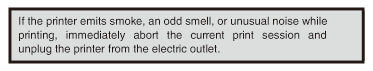
Should it occur, immediately turn the printer off, unplug it from the supply outlet,
and call your local Citizen Systems dealer.
|
   |
- Do not handle the printer in the following ways:
-
- Do not subject the printer to strong impacts or hard jolts (e.g., being stepped on,
dropped or struck).
- Never attempt to disassemble or modify the printer.
- These actions create the risk of printer damage, as well as product failure, overheating,
emission of smoke, fire, or electric shock.
They can also result in fire or electric shocks and so should always be avoided.
|
  |
- This device is not appropriate to be used where a child may be present. Install, store,
or use the device where it cannot be reached by a child.
-
- Electric appliances could cause an unexpected injury or accident if they are handled
or used improperly.
- Keep the power cord and signal cables out of the reach of children. Also children
should not be allowed to gain access to any internal part of the printer.
- The plastic bag the printer came in must be disposed of properly or kept away from
children. Wearing it over the head may lead to suffocation.
|
 |
PRECAUTIONS IN HANDLING THE PRINTER
WARNING
|
- Please observe the following precautions for power source and power cord:
-
- Do not plug or unplug the power cord with a wet hand.
- Use the printer only at the specified supply voltage and frequency.
- Use only the specified AC adapter with the printer.
- Use only the power cord that comes with the printer, and never use the supplied power
cord with another device.
- Check to make sure that the supply outlet from which the printer is powered has a
sufficient capacity.
- Do not supply the printer from a power strip or current tap shared with other appliances.
- Do not plug the power cord into an electric outlet with dust or debris left on the
plug.
- Do not use a deformed or damaged power cord.
- Do not move the printer while its power is on.
-
- Neglecting to handle it properly may result in printer failure, emission of smoke,
fire, or electric shock.
- An overload may cause the power cord to overheat, catch fire, or the circuit breaker
to trip.
- Do not allow anything to rest on the power cord. Do not place the printer where the
power cord may be stepped on.
- Do not subject the power cord to severe bending, twisting, or pulling. Do not carry
the product while it is in this state either.
- Do not attempt to modify the power cord unnecessarily.
- Do not place the power cord near any heating device.
-
- Neglecting these cautions may cause wires or insulation to break, which could result
in electric leakage, electric shock, or printer failure.
If the power cord sustains damage, contact your Citizen Systems dealer.
- Do not leave things around the electric outlet.
- Supply power to the printer from a convenient electric outlet, readily accessible
in an emergency.
-
- Pull the plug to immediately shut it down in an emergency.
- Insert the power plug fully into the outlet.
- If the printer will not be used for a long time, disconnect it from its electric outlet.
- Hold the plug and connector when plugging or unplugging the power cord or signal cable
after turning off the printer and the appliance connected to it.
|
      |
GENERAL OUTLINE
The CT-D101 line thermal printer series is designed for use with a broad array of terminal equipment
including data, POS, and kitchen terminals.
These printers have extensive features so they can be used in a wide range of applications.
EXPLANATION OF PRINTER PARTS
MAINTENANCE AND TROUBLESHOOTING
- EPSON and ESC/POS are registered trademarks of Seiko Epson Corporation.
- QR Code is a registered trademark of DENSO WAVE INCORPORATED.
- Ethernet is a registered trademark of Fuji Xerox Corporation.
- CITIZEN is a registered trademark of Citizen Watch Co., Ltd.
- All other trademarks are the property of their respective owners.
- Citizen Systems use these trademarks in accordance with the license of relevant owners.
Copyright© CITIZEN SYSTEMS JAPAN CO., LTD. 2021
Features
- High-speed printing at up to 250 mm/sec possible
- Silver ion-blended plastic is used for the exterior
- Stylish design
- Compact size with the lowest possible height
- Support for paper widths of 80 mm and 58 mm
- High-speed cutter employed
- Equipped with a paper anti-curling function
- Equipped with triple interface (USB, serial, Ethernet) or single interface (USB)
- Built-in drawer kick interface
- Energy saving function (ENERGY STAR compliant)
- USB-linked power OFF function available
- Paper saving function available
- Support for the JIS X0213 third and fourth level Kanji character sets
- Support for the simplified and traditional Chinese character sets and Hangul character
set
- Various customizations using the memory switches possible
- User created characters and logos can be saved in the user memory
- Support for barcodes including 2D barcodes
Unpacking
Make sure the following items are included with your printer.
| NAME |
QUANTITY |
ILLUSTRATION |
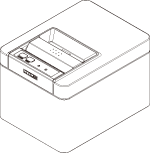
| Printer |
1 |
 |
| AC Adapter (37AD5) |
1 |
 |
| AC power cord* |
1 |
 |
| Quick Start Guide |
2 |
 |
* The specifications vary according to destination
Model Classification
Model numbers indicate printer features according to the following system.

- 1.Model name
- 2.Interface
-
UB: USB
-
TR: USB+Serial+Ethernet
- 3.Market
-
A: Asia
-
C: China
- 4.Body case color
-
WH: Pure white
-
BK: Black
Contact us in advance for special combinations, some of which may not be available.
Basic Specifications
| Item |
Specifications |
| Model |
CT-D101 |
| Print method |
Line thermal dot print method |
| Print widths |
72 mm/576 dots, 68.25 mm/546 dots, 64 mm/512 dots, 54.5 mm/436 dots, 54 mm/432 dots,
52.5 mm/420 dots, 48.75 mm/390 dots, 48 mm/384 dots, 45 mm/360 dots, factory default
72 mm
|
| Dot density |
8 × 8 dots/mm (203 dpi) |
| Print Speed |
250 mm/sec (maximum speed, print density level 100%, 2000 dot lines/sec)
|
| Number of print columns *1 |
Font |
Maximum number of characters (columns) / 80mm |
Maximum number of characters (columns) / 58mm |
Dot configuration
(dots)
|
| Font A |
48 |
35 |
12 × 24 |
| Font B |
64 |
46 |
9 × 24 |
| Font C |
72 |
52 |
8 × 16 |
| Kanji font A |
24 |
17 |
24 × 24 |
| Kanji font C |
36 |
26 |
16 × 16 |
| Character size *2 |
Font A:1.50×3.00 mm, Font B:1.13×3.00 mm, Font C:1.00×2.00 mm, Kanji font A:3.00×3.00
mm, Kanji font C:2.00×2.00 mm
|
| Character type |
Alphanumeric characters, international characters, PC437/737/850/852/857/858/860/862/863/864/865/866,
WPC1251/1252/1253/1255/1258, Katakana, ThaiCode 11/18 (1Pass/3Pass), TCVN-3, Kanji (JIS first, second,
third, and fourth level), Kana, extended characters, JIS X0213, GB18030, BIG5, KS Hangul, EUC Hangul
|
| User memory |
384 KB (capable of storing user-defined characters and logos) |
| Bar code types |
UPC-A/E, JAN(EAN) 13 digits/8 digits, ITF, CODE39, CODE128, CODABAR (NW-7), CODE93,
PDF417, QR Code, GS1-DataBar
|
| Line spacing |
4.25 mm (1/6 inch) (Variable by command) |
| Paper roll |
Roll paper: 80 mm x max. ø83 mm
Paper thickness: 53 to 85 μm (paper roll inner diameter 12 mm / outer diameter 18
mm)
|
| Interface |
USB, USB+serial+Ethernet |
| Cash drawer kick-out |
Supports 2 cash drawers |
| Input buffer |
4 K bytes/45 bytes |
| Supply voltage |
DC 24 V ±5% |
| Power consumption |
Approx. 45 W (when printing), approx. 1 W (in standby mode), approx. 0.3 W (with power
off)
|
AC Adapter
(37AD5)
|
Rated input: AC 100 to 240 V, 50/60 Hz, 150 VA
Rated output: DC 24 V, 2.1 A
|
| Weight |
Approximately 1.2 kg |
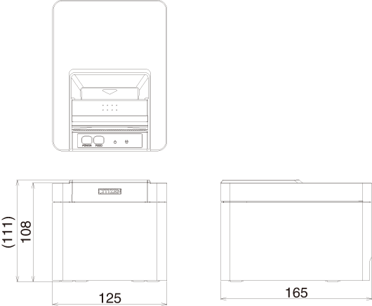
| Outside dimensions |
125 (W) × 165 (D) × 108 (H) mm |
| Operating temperature and humidity |
5 to 45 °C, 10 to 90% RH (no condensation)
|
| Storage temperature and humidity |
-20 to 60 °C, 10 to 90% RH (no condensation)
|
| Reliability |
Print head life: 150 km, 200 million pulses (room temperature, room humidity, specified
recommended paper, specified paper thickness), Auto cutter life: 1.5 million cuts
(3-inch), 1 million cuts (2-inch) (room temperature, room humidity, specified recommended
paper, specified paper thickness)
|
| Safety standard *3 |
UL, cUL, FCC, IC, CE, UKCA *4 |
Notes:
*1 The number of printable columns is selected using a memory switch.
The numbers of columns noted in this table refer to typical models. The number of
columns varies depending on specifications.
*2 Characters appear small because the dimensions include a blank area surrounding
each character.
*3 This standard applies when our AC Adapter (37AD5) is used.
*4 Please contact us for information on other regions and the latest status such as standardnumbers.
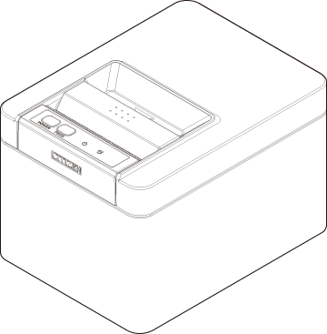
Printer Appearance
Names of parts
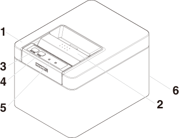
- 1.Paper cover
-
Open to load paper.
Also open to clear a cutter error.
-
- 2.Cover open lever
-
Use to open and close the paper cover.
- 3.POWER button
-
Hold down two or three seconds to switch power on or off.
- 4.FEED button
-
Press this button to feed paper.
In case of a cutter error, press the FEED button with the paper cover closed after removing the cause.
The printer enters the mode for setting memory switches and running self test.
-
-
- 5.Operation panel
- 6.Rear connectors
Operation panel

Two LEDs and two keys are placed on the operation panel.
|
LED name |
Description |
 |
POWER LED |
Turns on when the power is turned on and turns off when the power is turned off.
Flashes when a memory error occurs and when data is being received.
|
 |
ERROR LED |
Flashes when the print head is hot, when the paper cover is open, when a cutter error
occurs, and so on.
|
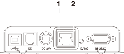
Rear connectors
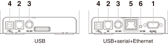
- 1.Serial connector
- 2.Cash drawer kick-out connector
-
Connect to the cable from the cash drawer.
- 3.Power connector
-
Connect to the AC adapter cable.
- 4.USB connector
- 5.Ethernet connector
- 6.Panel button
-
The current configuration information can be printed.
For details, refer to “Ethernet (LAN) Interface” in Section 3.3.
-
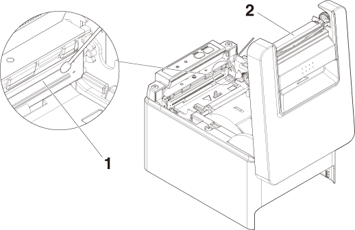
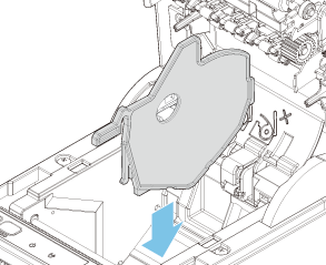
Inside the Paper Cover
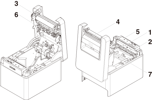
- 1.Print head (thermal)
-
Prints characters and graphic data on paper (paper rolls).
- 2.Paper end (PE) sensor
-
Detects when there is no paper. Printing stops when this sensor detects there is no
paper.
- 3.Platen
-
Feeds the paper.
Do not remove the platen except to do maintenance.
- 4.Auto cutter
-
Cuts the paper.
-
- 5.Manual cutter
-
For cutting the paper manually when printing is finished.
- 6.Paper anti-curling roller
-
Roller for reducing the warp of the paper.
- 7.Paper anti-curling damper
-
Damper for reducing the warp of the paper.
Notes
- The anti-curling roller and anti-curling damper do not straighten the paper completely.
Other Built-in Functions
- Buzzer
-
Buzzes when errors occur or when operations or command operations are performed.
-
- User memory
-
You can save user-defined logo and character data in this memory. Data remains stored
in this memory even if the printer is turned off. For information on how to save data,
refer to the Command Reference.
- Memory switch
-
Setting of various kinds of functions can be stored in memory. Settings remain stored
in the memory even if the printer is turned off.
- USB-linked power OFF (When MSW6-3 of memory switch is set to ON)
-
When the printer is connected to PC by USB, the printer becomes the state of USB-linked
power OFF after 3 seconds when PC power off or USB connection lost.
This mode is canceled when the PC is turned back on or when a USB connection is established.
Notes
- Since the POWER LED is unlit when the state of USB-linked power OFF, it cannot be identified from the
power OFF.
- Pressing the POWER button while the state of USB-linked power OFF turns on power normally.
CAUTION
- Remove the partially cut paper before performing back feed for starting printing.
The cut paper may be torn off in the next printing process, which may cause a problem.
- Auto side shift (MSW8-6)
-
This function dissipates heat load during frequent heat generation by a vertical ruled
line or other specific head heating element.
-
If no data is received within 15 seconds after each cut or print, the print position is automatically slid N* dots
to the right. The original print position is returned to at the next slide timing.
-
* N is the MSW8-6 setting value.
Notes
- If the right margin is too narrow, this may result in some print characters being
cut off.
- This function is disabled under initial settings.
- To enable this function, use MSW8-6 to specify an appropriate value for the maximum
slide amount.
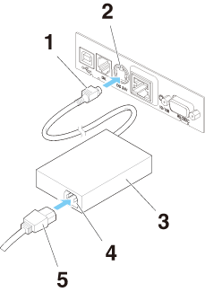
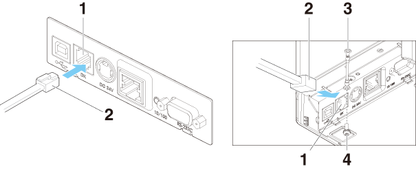
Connecting the AC Power Cord
- 1.Turn off the power.
- 2.Connect the power connector to the AC adapter cable connector.
Next, connect the AC power cord to the AC inlet, and insert the plug into an electric
outlet.
- 1.Cable connector
- 2.Power connector
- 3.AC adapter
- 4.AC inlet
- 5.AC power cord
CAUTION
- Use only the specified AC adapter.
- Always hold the AC adapter’s cable connector by the connector when removing or inserting
it.
- Use an AC power source that does not also supply power to equipment that generates
electromagnetic noise.
- Pulling on the AC power cord may damage it, cause a fire, electric shock, or break
a wire.
- If a lightning storm is approaching, unplug the AC power cord from the electric outlet.
A lightning strike may cause a fire or electric shock.
- Keep the AC power cord away from heat generating appliances. The insulation on the
AC power cord may melt and cause a fire or electric shock.
- If the printer is not going to be used for a long time, unplug the AC power cord from
the electric outlet.
- Place the AC power cord so that people do not trip on it.
- Be sure to unplug the AC power cord when connecting the cable connector to the power connector. If the AC power cord is left plugged into the electric outlet, the 24 V and GND terminals of the cable connector may come into contact with the screw head or other metal parts and cause a short circuit, resulting in malfunction of the AC adapter.
Connecting Interface Cables
- 1.Turn off the power.
- 2.Orient the interface cable correctly and insert it into the interface connector.
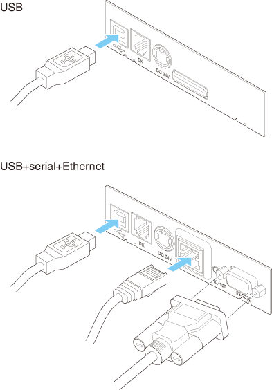
CAUTION
- When disconnecting the cable, always hold the connector.
- Be careful not to insert the USB cable into the cash drawer kick-out connector.
- Hold the connector of the LAN cable perpendicular and straight when connecting or
disconnecting it. Doing it at an angle may cause the connector to misconnect.
Notes
- To connect more than one printer to a single computer by USB, you must change the
serial number of the USB interface.
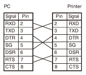
Use a serial cable with the connection layout shown below.
9-pin (female) - 9-pin (female) cable
CAUTION
- Place the interface cable so that people do not trip on it.
Ethernet (LAN) Interface
The following describes an overview of the Ethernet (LAN) interface.
For details on this function, refer to a separate manual.
Note that the Ethernet (LAN) interface is not available in the USB model.
Panel button operation
The function of the panel button is as follows.
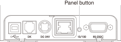
- Printing network setup information
-
Press the panel button.
- Returning to factory settings
-
Hold down the panel button. A buzzer* will sound and then hold down the panel button
again within 3 seconds. It returns network settings to its factory settings.
-
* Depending on settings, the buzzer may not sound.
Notes
- The board will automatically restart after this operation is complete.
- If settings are configured to obtain an IP address from a DHCP server automatically,
the new IP address may be different from the previous one.
LED Functions
The tables below explain how to interpret LED indications.
- 1.Network transmission speed
-
| Transmission speed |
LED (green) |
| 100 Mbps |
Lit |
| 10 Mbps/Not connected |
Unlit |
- 2.Network status
-
| Status |
LED (yellow) |
| Connected |
Lit |
| Not connected |
Unlit |
| Data transmission in progress |
Flashing |
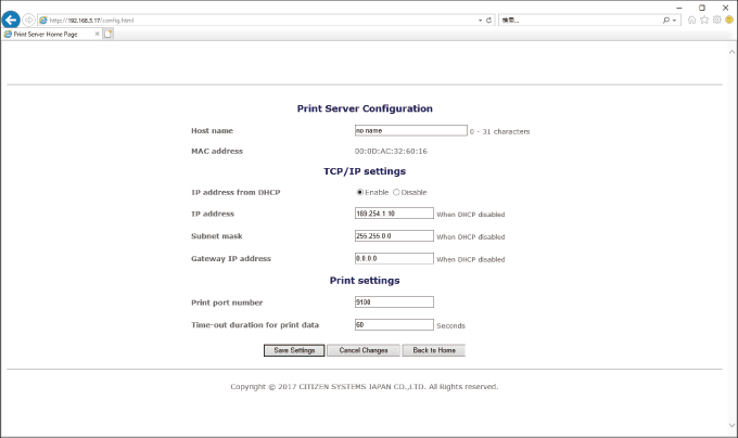
Changing network settings
You can use a web browser to access a special settings page to check and change board
settings.
- Access the special settings page
- 1.Use a web browser to access the URL of the special settings page. Enter the IP address
assigned to the printer as the part of URL. (Example: For an IP address of 169.254.1.10,
input: http://169.254.1.10.)
- 2.This displays the page to display the current status.
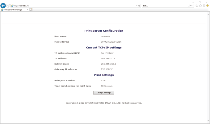
- 3.Press the [Change Settings] button to enter the following Change Settings screen.
For details, refer to a separate manual.
Connecting the Cash Drawer
- 1.Turn off the power.
- 2.Confirm the orientation of the cash drawer kick-out cable connector and connect it
to the cash drawer kick-out connector at the back of the printer.
- 3.Remove the screw for the ground wire.
- 4.Screw the cash drawer’s ground wire to the body of the printer.
- 1.Cash drawer kick-out connector
- 2.Cash drawer kick-out cable connector
- 3.Ground wire
- 4.Screw for ground wire
|
CAUTION
- Connect only the cash drawer kick-out cable to this connector. (Do not connect a telephone
line.)
- Hold the connector of the drawer kick cable perpendicular and straight when connecting
or disconnecting it. Doing it at an angle may cause the connector to misconnect.
Notes
- Signals cannot be output from the cash drawer kick-out connector while printing.
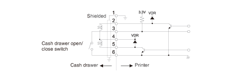
- (1)Connector pin configuration
-
| No. |
Signal |
Function |
 |
| 1 |
FG |
Frame ground |
| 2 |
DRAWER1 |
Cash drawer 1 drive signal |
| 3 |
DRSW |
Cash drawer switch input |
| 4 |
VDR |
Cash drawer drive power supply |
| 5 |
DRAWER2 |
Cash drawer 2 drive signal |
| 6 |
GND |
Signal ground (common ground on circuits) |
-
* Connector used:TM5RJ3-66 (Hirose) or equivalent
* Applicable connector: TM3P-66P (Hirose) or equivalent
- (2)Electric characteristics
-
- 1)Drive voltage: 24 VDC
- 2)Drive current: Approx. 1 A max. (not to exceed 510 ms.)
- 3)DRSW signal: Signal levels: “L” = 0 to 0.5 V, “H” = 3 to 5 V
- (3)DRSW signal
- Status can be tested by commands.
- (4)Drive circuit
-
Cash drawer kick-out connector
CAUTION
- Cash drawers 1 and 2 cannot be operated at the same time.
- The solenoid used for the cash drawer should be 24 Ω or more. Do not allow the electric
current to exceed 1 A. Excessive current could damage or burn out the circuits.
Precautions for Installing the Printer
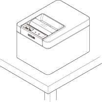
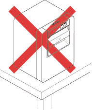
This product can be used horizontally or wall-mounted. Cannot be used vertically.
 |
 |
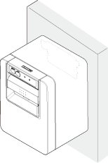 |
| Horizontal position |
Vertical position |
Wall-mounted |
CAUTION
- Do not use the printer under the following conditions.
-
- Avoid locations subject to vibration or instability.
- Locations that are very dirty or dusty.
- Avoid locations where the printer is not level.
-
- The printer may fall and cause an injury.
- The quality of printing may deteriorate.
- Oriented other than as specified.
-
- Malfunction, failure, or electric shock may result.
- Precautions for horizontal installations
-
- Do not use the full cut setting. Doing so could cause a cutter jam.
For wall mounting
If the printer is to be wall-mounted, ask a service person to install it.
For more information, please refer to the separate Wall Mount Kit manual.
Loading Paper
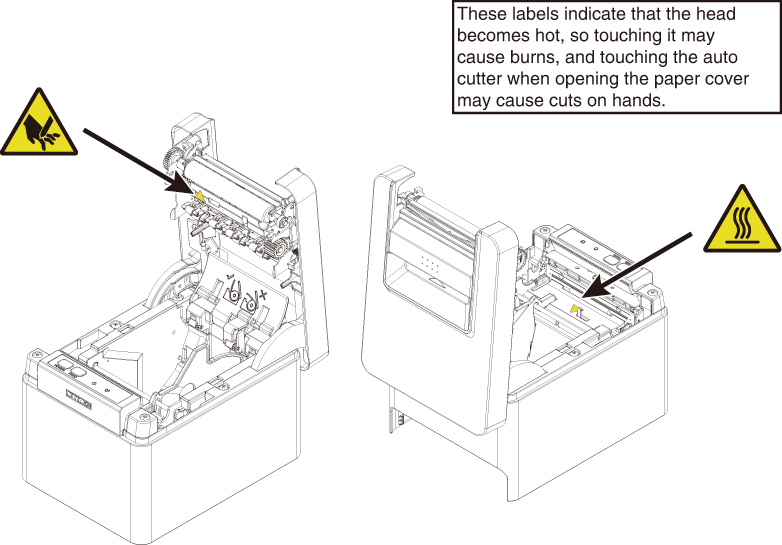
CAUTION
- When opening the paper cover, be careful not to touch the entrance of the blade of
the auto cutter.
- The print head is very hot immediately after printing. Be careful not to touch it
with your hands.
- Do not touch the print head with bare hands or metal objects.
- When closing the paper cover, be careful not to pinch your fingers.
- Be careful of paper cuts while loading the paper.
Notes
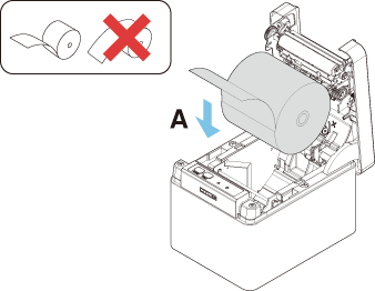
- Always use the specified types of paper rolls.
- Confirm that the paper roll is set correctly.
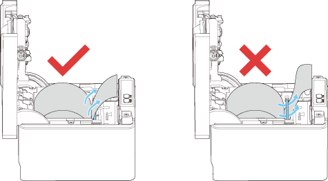
- If the paper is skewed and not coming straight out of the paper cover, open it and
straighten the paper.
- Always pull a few centimeters of paper straight out of the printer if you open the
paper cover while paper is loaded.
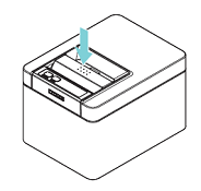
- Press on the center of the paper cover to close it securely.
- If only one of them is closed, uneven printing may occur.
58-mm Width Roll Paper Partition
- 1.Turn off the power.
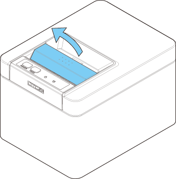
- 2.Pull the cover open lever toward you to open the paper cover.
- 3.Mount the supplied partition to the groove. When using the 80-mm width roll paper, remove the partition.
- 4.Change the print area width while referring to “Manual Setting of Memory Switches”
in Section 5.3.
-
CAUTION
- When opening the paper cover, be careful not to touch the entrance of the blade of
the auto cutter.
- The print head is very hot immediately after printing. Be careful not to touch it
with your hands.
- Do not touch the print head with bare hands or metal objects.
Notes
- When using 58-mm wide paper, use the printer as a dedicated printer for that paper size.
The printer may not correctly feed paper or print if it is switched to 80-mm wide paper after using 58-mm wide paper.
Precautions for Creating Applications and Practical Operations
If printing is done immediately after the paper is partially cut and torn off, the
top of the next print out may be distorted.
For printing after cutting, we recommend to print with the first line empty.
If you are using a serial interface that has a slow data transmission speed, streaks
may appear in the printouts when you are printing graphics or gradated text, which
require large amounts of data.
USB interfaces may be susceptible to the effects of electromagnetic interference from
the host or environment.
If this is the case, try using a cable with ferrite cores on both ends, which are
very effective at eliminating EMI.
Download Site for Various Electronic Files
You can view support information and download the latest documents, drivers, utilities,
etc. from the following site.
Periodic Cleaning
How to care for the printer’s exterior surface
After turning off the printer, wear gloves and use a soft cloth or an absorbent cotton
to wipe it off.
At this time, be sure to unplug the AC power cord from the outlet.
CAUTION
- Prolonged use of cleaning agents may cause whitening of the outer case.
- When cleaning with an approved chemicals, test it beforehand and always refer the
manufacturer's recommended procedure.
- Do not clean with Ethanol where fire is present, as Ethanol is extremely flammable.
- Utilize a soft cloth when spreading chemicals onto printer. Do not spray or pour directly
onto printer.
- Wipe off the disinfectant with a soft damp cloth after cleaning procedure. No water
droplets should remain on the printer.
- Do not soak or wipe the inside of the printer nor allow disinfectant gets inside.
It may cause a product failure.
How to clean the print head and platen
If the print head, platen, or other parts of the printer are dirty, the printer may
not print cleanly or it could cause a malfunction. It is recommended that you clean
the unit periodically (approximately two to three months) using the following procedure.
CAUTION
- When opening the paper cover, be careful not to touch the entrance of the blade of
the auto cutter.
- The print head is very hot immediately after printing. Be careful not to touch it
with your hands.
- Do not touch the print head with bare hands or metal objects.
Clearing a Cutter Error
If the auto cutter stops during the auto cutter operation with the blade of the auto
cutter in the open position due to foreign matter entering, paper jamming, etc., the
ERROR LED flashes.
When a cutter error occurs, resolve the cutter error with the following procedure.
- 1.Turn off printer power.
- 2.Flip up the cover open lever to open the paper cover.
- 3.Remove any jammed paper including any scraps of paper. (Remove the paper roll that
is loaded in the holder also.)
- 4.Reload the paper roll and close the paper cover.
- 5.Turn on the power.
CAUTION
- When opening the paper cover, be careful not to touch the entrance of the blade of
the auto cutter.
- The print head is very hot immediately after printing. Be careful not to touch it
with your hands.
- Do not touch the print head with bare hands or metal objects.
Self Test
You can use self test to check for printer problems.
Performing a self test operation
- 1.While paper is loaded, press and hold the FEED button and turn on the power.
- 2.Hold the FEED button down for about one second until the buzzer sounds. Release the button to start
self test. The printer will print its model name, version, memory switch settings,
and built-in fonts.
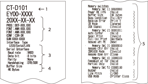
- 1.Printer type name
- 2.Firmware version
- 3.Interface settings
- 4.Buffer size
- 5.Memory switch settings
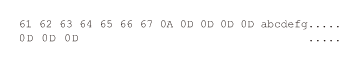
Hexadecimal Dump Printing
Print received data in hexadecimal. If problems such as missing or duplicated data
occur, this function allows you to check whether or not the printer is receiving data
correctly.
How to do hexadecimal dump printing
- 1.Load paper.
- 2.While the paper cover is open, hold down the FEED button as you turn on printing power. Keep FEED button pressing until the POWER LED starts to flash, and then close the paper cover.
- 3.The printer will print “HEX dump print mode” followed by the received data printed
in hexadecimal numbers and some characters.
How to stop hexadecimal dump printing
Do one of the following to stop printing.
- Press the FEED button consecutively three times
- Turn off the power
- Receive a reset command from an interface
Notes
- The printer prints “.” if there is no character corresponding to the data.
- None of the commands function during hexadecimal dump printing.
- If print data does not cover a complete line, press the FEED button to advance the paper.
Print example
HEX dump print mode
Error Indications
- Paper End
If the paper ends, the ERROR LED lights and a buzzer sounds. Load a new paper roll. The buzzer may not sound depending
on the memory switch setting.
- Cover Open
If the cover is opened, the ERROR LED lights.
The buzzer may also sound depending on the memory switch setting.
Do not open the cover during printing. If the cover is accidentally opened, the ERROR LED flashes. Check the paper, pull it straight out of the printer by a couple of centimeters,
and then close the cover. Printing restarts. A command must be sent to restart printing
depending on the memory switch setting.
- Cutter Error
If the auto cutter stops due to paper jamming, etc., the ERROR LED flashes. Remove the cause and press the FEED key. If the auto cutter still does not move and the paper cover cannot be opened,
refer to “Clearing a Cutter Error.”
-
- Print Head Hot
Dense printing, heavy black printing, and continuous printing in a high temperature
environment increase the temperature of the print head. When the print head exceeds
a certain temperature, the printer stops printing and waits until the temperature
of the print head decreases. The ERROR LED flashes during this time. When the temperature decreases, printing restarts automatically.
The status display for various messages is shown below.
| Status |
POWER LED (green)
|
ERROR LED (red)
|
Buzzer sound *3 |
| Paper End |
Lit |
Lit |
Yes |
| Cover open*1 |
Lit |
Lit |
No |
| Cover open II*2 |
Lit |
 |
No |
| Cutter Error |
Lit |
 |
Yes |
| Memory Error |
 |
- |
No |
| Print Head Hot |
Lit |
 |
No |
| Low-voltage Error |
Lit |
 |
No |
| High-voltage Error |
Lit |
 |
No |
| System Error |
Lit |
 |
No |
| Wait for Macro Execution |
 |
Unlit |
No |
| Data reception |
 |
Unlit |
No |
Notes
*1 Indicated when a cover is opened during standby.
*2 Indicated when a cover is opened during printing.
*3 The buzzer sounds when MSW5-1 (buzzer setting) is enabled.
However, the condition that the buzzer sounds varies depending on the MSW5-1 and MSW10-5
settings.
Paper Jams
Take care to avoid obstruction of the paper outlet and paper jamming around the outlet
during printing.
If paper cannot get out of the printer, it can roll up on the platen inside the printer
and cause an error.
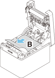
If the paper wraps around the platen, open the paper cover and carefully pull the
paper out.
Precautions for Performing Printing for Which Printing Speed Changes
When printing for which the printing speed changes is performed, white lines may be
printed or paper may not be fed depending on the printing conditions. To prevent these
problems, change the following memory switch settings.
- 1.Enable MSW2-3 (buffering).
- 2.Increase the baud rate of MSW7-1 (serial baud rate).
- 3.Change MSW10-2 (print speed) to a lower level.
Notes
- Depending on the serial interface transmission speed, ambient temperature, print data
duty, and other factors, changing the above settings may not eliminate the problems.
External Views and Dimensions
(Unit: mm)
Printing Paper
Use the paper shown in the following table or paper of the same quality.
| Paper type |
Product name |
| Recommended thermal roll paper |
Nippon Paper TP50KR-2Y, TP50KJ-R, TL69KS-LH, TF50KS-E2D
Oji Paper PD150R, PD160R, PD160R-63
Mitsubishi Paper Mills HP220AB-1, P220AB
Koehler KT48-FA
|
(Unit: mm)
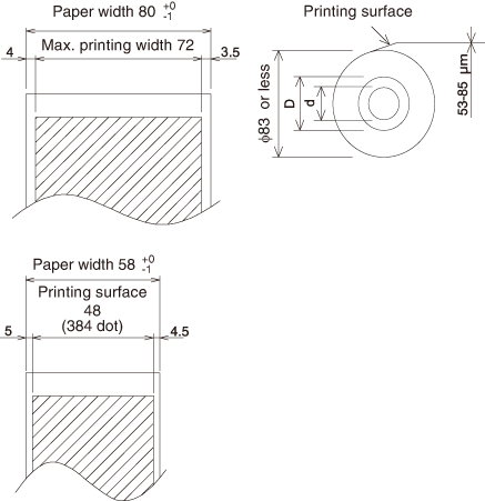
| Paper thickness (μm) |
53 to 85 |
| Core inner diameter d (mm) |
ø12 |
| Core outer diameter D (mm) |
ø18 |
Notes
- Use thermal paper that is wound as follows:
-
- Not creased and fits tight to the core.
- Not folded.
- Not glued to the core.
- Rolled with the printable side out.
Manual Setting of Memory Switches
Memory switches are used to set various printer settings. Memory switches can be set
manually, or by utilities or commands. This section explains how to perform manual
settings.
For information on how to set the memory switches using commands, please refer to
the Command Reference.
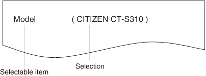
Quick setting mode
The settings for the memory switches for a replacement printer’s manufacturer, model,
paper width, and character spacing can be set at the same time to the optimum settings.
Do the settings while confirming the selected items on the printout.
- 1.Load paper.
- 2.While the paper cover is open, press and hold the FEED button and turn on the power.
- 3.Press the FEED button three and close the paper cover.
-
The printer enters memory switch quick setting mode.
-
The selectable item “Model” and the selection are printed.
- 4.Press the FEED button.
-
A selection is printed in order through the cycle each time the FEED button is pressed.
-
Press the FEED button until the selection you want is printed.
- 5.Press the FEED button for at least two seconds.
-
The selection is set.
-
If there is another selectable item, it and the selection are printed.
- 6.Repeat steps 4 and 5 to select and set the printer’s model, paper width, character
spacing (EPSON T88 only).
-
When all the items are set, “Save To Memory” is printed.
- 7.Press the FEED button for at least two seconds.
-
The changed memory switch settings are saved and a list of them is printed.
-
The printer exits quick setting mode when printing is finished.
| Selected item |
|
Automatic memory switch settings |
| Manufacturer |
Paper
width |
Character
space |
 |
MSW2-4
Full Col
Print |
MSW3-7
CBM1000
Mode |
MSW8-1
Print Width |
MSW6-2
Character
Space |
CITIZEN
CT-S310
|
58 mm |
- |
WaitData |
Invalid |
384 dots |
- |
| 80 mm |
- |
WaitData |
Invalid |
576 dots |
- |
EPSON
T88
|
58 mm |
0 dot |
WaitData |
Invalid |
360 dots |
0 dot |
| 1 dot |
WaitData |
Invalid |
390 dots |
1 dot |
| 80 mm |
0 dot |
WaitData |
Invalid |
512 dots |
0 dot |
| 1 dot |
WaitData |
Invalid |
546 dots |
1 dot |
EPSON
203dpi
|
80 mm |
- |
WaitData |
Invalid |
576 dots |
0 dot |
| 58 mm |
- |
WaitData |
Invalid |
420 dots |
- |
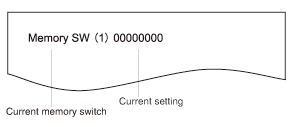
Individual setting mode
Set the memory switches individually.
Do the settings while confirming the memory switch function and settings on the printout.
- 1.Load paper.
- 2.While the paper cover is open, press and hold the FEED button and turn on the power.
- 3.Press the FEED button twice and close the paper cover.
-
The printer enters the mode for setting memory switches individually.
-
The printer prints “Memory SW (1)” and the current setting, 0 (off) or 1 (on).
-
(The current settings for memory switches 7 to 13 are not printed.)
- 4.Press the FEED button.
-
Each press of the FEED button cycles through the list of memory switches in the following sequence: “Memory
SW (1)” > “Memory SW (2)” > ...“Memory SW (11)” or “Memory SW (13)” > “Save To Memory”
> “Memory SW (1)”.
-
Press the FEED button until the number for the memory switch you want to change is printed.
- 5.Press the FEED button for at least two seconds.
-
A setting for the memory switch is printed, through the cycle, each time the FEED button is pressed for at least two seconds.
-
Press the FEED button for at least two seconds to cycle through the list until the function of the
memory switch you want to change is printed.
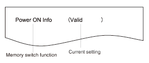
- 6.Press the FEED button.
-
A setting is printed each time the FEED button is pressed in order through the cycle.
-
When the current settings are printed, the COVER LED lights.
-
Press the FEED button until the setting you want is printed.
- 7.Press the FEED button for at least two seconds.
-
The selected settings are set.
-
The next memory switch function and settings are printed.
- 8.Repeat steps 5 to 7 to change different functions for the current memory switch number.
- 9.Open the paper cover and close it.
-
The changed memory switch settings are printed.
- 10.Repeat steps 4 to 9 to change functions for a different memory switch number.
- 11.Press the FEED button until “Save To Memory” is printed.
- 12.Press the FEED button for at least two seconds.
-
The changed memory switch settings are saved and a list of them is printed.
-
The printer exits individual setting mode when printing is finished.
Memory switch initialization
Set all the memory switches to the factory settings.
The function of each memory switch is shown in the following table. (Shaded values
are factory settings.)
| Switch no. |
Function |
OFF |
ON |
| MSW1-1 |
Power ON Info |
Valid |
Not Send |
| MSW1-2 |
Buffer Size |
4K bytes |
45 bytes |
| MSW1-3 |
Busy Condition |
Full/Err |
Full |
| MSW1-4 |
Receive Error |
Print“?” |
No Print |
| MSW1-5 |
CR Mode |
Ignored |
LF |
| MSW1-6 |
Reserved |
Fixed |
— |
| MSW1-7 |
DSR Signal |
Invalid |
Valid |
| MSW1-8 |
INIT Signal |
Invalid |
Valid |
|
|
|
|
| MSW2-1 |
Reserved |
— |
Fixed |
| MSW2-2 |
Auto Cutter |
Invalid |
Valid |
| MSW2-3 |
Spool Print |
Invalid |
Valid |
| MSW2-4 |
Full Col Print |
LineFeed |
WaitData |
| MSW2-5 |
Resume aft PE |
Next |
Top |
| MSW2-6 |
Reserved |
Fixed |
— |
| MSW2-7 |
Reserved |
Fixed |
— |
| MSW2-8 |
Reserved |
Fixed |
— |
|
|
|
|
| MSW3-1 |
Resume Cttr Err |
Valid |
Invalid |
| MSW3-2 |
Reserved |
Fixed |
— |
| MSW3-3 |
Reserved |
Fixed |
— |
| MSW3-4 |
Reserved |
Fixed |
— |
| MSW3-5 |
Reserved |
Fixed |
— |
| MSW3-6 |
Reserved |
Fixed |
— |
| MSW3-7 |
CBM1000 Mode |
Invalid |
Valid |
| MSW3-8 |
Resume Open Err |
Close |
Command |
|
|
|
|
| MSW4-1 |
Reserved |
Fixed |
— |
| MSW4-2 |
Reserved |
Fixed |
— |
| MSW4-3 |
Feed&Cut at TOF |
Invalid |
Valid |
| MSW4-4 |
Reserved |
Fixed |
— |
| MSW4-5 |
Reserved |
Fixed |
— |
| MSW4-6 |
Reserved |
Fixed |
— |
| MSW4-7 |
Reserved |
Fixed |
— |
| MSW4-8 |
Partial Only |
Invalid |
Valid |
|
|
|
|
| MSW5-1 |
Buzzer |
Valid |
Invalid |
| MSW5-2 |
Line Pitch |
1/360 |
1/406 |
| MSW5-3 |
USB Mode |
Virtual COM |
Printer Class |
| MSW5-4 |
Reserved |
Fixed |
— |
| MSW5-5 |
Reserved |
Fixed |
— |
| MSW5-6 |
Reserved |
Fixed |
— |
| MSW5-7 |
Reserved |
Fixed |
— |
| MSW5-8 |
Reserved |
Fixed |
— |
|
|
|
|
| MSW6-1 |
Act. For Driver |
Invalid |
Valid |
| MSW6-2 |
Character Space |
Invalid |
Valid |
| MSW6-3 |
USB Power Save |
Invalid |
Valid |
| MSW6-4 |
Reserved |
Fixed |
— |
| MSW6-5 |
Reserved |
Fixed |
— |
| MSW6-6 |
Reserved |
Fixed |
— |
| MSW6-7 |
Reserved |
Fixed |
— |
| MSW6-8 |
Power ON trigger |
Power switch ON |
AC power input |
| Switch no. |
Function |
Initial setting |
Setting value |
| MSW7-1 |
Baud Rate |
9600 bps |
1200 bps, 2400 bps, 4800 bps, 9600 bps, 19200 bps, 38400 bps, 57600 bps, 115200 bps |
| MSW7-2 |
Data Length |
8bits |
7bits, 8bits |
| MSW7-3 |
Stop Bit |
1bit |
1bit, 2bits |
| MSW7-4 |
Parity |
NONE |
NONE, ODD, EVEN |
| MSW7-5 |
Flow Control |
DTR/DSR |
DTR/DSR, XON/XOFF |
| MSW7-6 |
DMA Control |
Valid |
Valid, Invalid |
| MSW7-7 |
VCom Protocol |
PC Setting |
PC Setting, DTR/DSR, XON/XOFF |
|
|
|
|
| MSW8-1 |
Print Width |
576 dots |
576 dots, 546 dots, 512 dots, 436 dots, 432 dots, 420 dots, 390 dots, 384 dots, 360
dots
|
| MSW8-3 |
Top Margin |
12 mm |
3 mm, 4 mm, 5 mm, 6 mm, 7 mm, 8 mm, 9 mm, 10 mm, 11 mm, 12 mm |
| MSW8-4 |
Line Gap Reduce |
Invalid |
Invalid, 3/4, 2/3, 1/2, 1/3, 1/4, 1/5, ALL |
| MSW8-5 |
Reduced Char V/H |
100% / 100% |
100% / 100%, 75% / 100%, 50% / 100%, 100% / 75%, 75% / 75%, 50% / 75% |
| MSW8-6 |
Auto Side Shift |
Invalid |
Invalid, 1 dot, 2 dots, 3 dots, 4 dots, 5 dots, 6 dots, 7 dots |
|
|
|
|
| MSW9-1 |
Code Page |
PC437 |
Katakana, PC 437, PC 737, PC 850, PC 852, PC 857, PC 858, PC 860, PC 862, PC 863, PC 864, PC 865, PC 866,
WPC1251, WPC1252, WPC1253, WPC1255, WPC1258, Space page, ThaiCode11 1Pass, ThaiCode11 3Pass, ThaiCode18 1Pass,
ThaiCode18 3Pass, TCVN-3
|
| MSW9-2 |
Int’Char Set |
U.S.A
China*
|
USA, France, Germany, England, Denmark, Sweden, Italy, Spain, Japan, Norway, Denmark
2, Spain 2, Latin America, Korea, Croatia, China, Vietnam
|
| MSW9-4 |
Kanji code |
Invalid,
GB18030
(CHN)*
|
Disabled, JIS (Japan), SJIS: CP932 (Japan), SJIS: X0213 (Japan), GB18030 (China),
KS Hangul (South Korea), EUC Hangul (South Korea), BIG5 (Taiwan)
|
|
|
|
|
| MSW10-1 |
Print Density |
100 % |
70 %, 75 %, 80 %, 85 %, 90 %, 95 %, 100 %, 105 %, 110 %, 115 %, 120 %, 125 %, 130
%, 135 %, 140 %
|
| MSW10-2 |
Print Speed |
Level 9 |
Level 1, Level 2, Level 3, Level 4, Level 5, Level 6, Level 7, Level 8, Level 9 |
| MSW10-4 |
Old Command |
Invalid |
Invalid, CBM1, CBM2 |
| MSW10-5 |
Buzzer Event |
Not By C. Open |
All Event/Error, Not by C.Open, Not by C.Open/PE |
| MSW10-6 |
Buzzer Sound |
Tone 2 |
Tone 1, Tone 2, Tone 3, Tone 4 |
* The specifications vary according to destination

 DAILY MAINTENANCE